MPO/MTP Cabling System

Karono manufactures and distributes a wide range of MTP/MPO products including Single-mode or Multimode MPO and MTP fiber cable.  Multi fiber ferrule connections used in high-density backplane and Printed Circuit Board (PCB) applications in data and telecommunications systems.  High density MTP/MPO trunk cables with up to 288 fibers in a single cable.  The MPO fiber cable connector offers up to 12 times the density of standard connectors, providing significant space and cost savings.

The MPO/MTP connector, specified and standardized in IEC 61754-7 and TIA/EIA 604-5, beside the LC fiber optic interface is the first choice for ITS (Information Telecommunication System) in tomorrow‘s bandwidth-hungry, high speed commercial buildings and data centers. It can be either used for parallel optics applications such as Infiniband with data rates up to 120 Gb/s and for the upcoming 40 Gb/s and 100 Gb/s Ethernet protocols via Multimode OM3, OM4 and OS2 fiber. Similar to the well-known MT-RJ connector, the MPO/MTP houses several fibers in one single high-precision ferrule that can be PC or APC polished with a typical insertion loss of 0.25 dB, return loss of >60 dB for Singlemode and insertion loss of 0.2 dB, return loss >30 dB for Multimode..

The MPO/MTP fiber cable can be mass terminated in combinations of 4, 8, 12, 24 and 48 fiber ribbon cables. Optional Lengths available.

MPO/MTP FIBER OPTIC CABLES

8,12,16,24,32 fibers MPO/MTP Fiber Cables

MPO/MTP FIBER OPTIC FANOUT CABLES

8,12 fibers MPO/MTP Fiber Fanout Cables

MPO/MTP FIBER LOOPBACK TESTER

12,16,24,32 fibers MPO/MTP Loopbacks

MPO/MTP FIBER OPTIC ADAPTERS

MPO/MTP Fiber Adapters

What is MPO Connector

Multi-Fiber Push On (MPO) is a fiber optic connector category that utilizes a linear array of fibers across a single ferrule. The most common application for MPO connectors is the termination of multi-fiber ribbon connections in high-density indoor environments.
MPO connectors have been a standard interface for dense trunk cables and have become more widely used recently in patch panel, server and switch applications. A single MPO connector can replace multiple “Sam Charlie” (SC) or LC connections, providing space savings with 12 times (or more) the fiber density in an equivalent footprint size while simplifying installation. The MPO connection interface has been defined within the IEC-61754-7 (international) and TIA 604-5 (U.S.) standards.
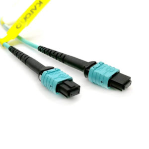
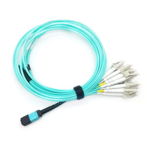
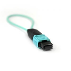
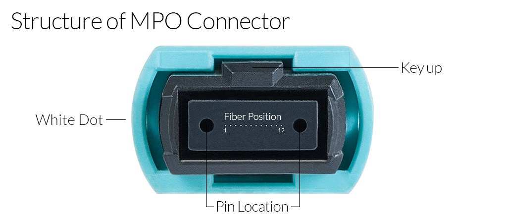
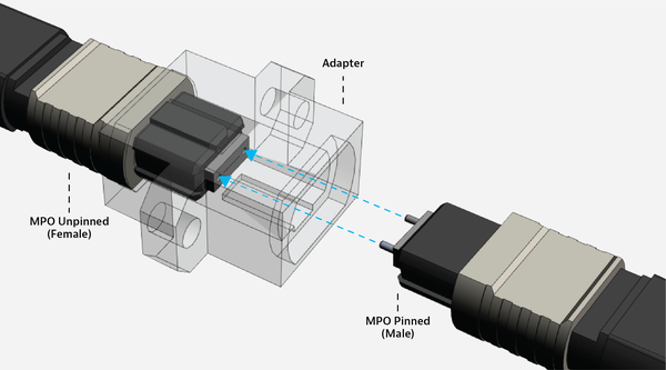
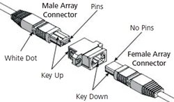
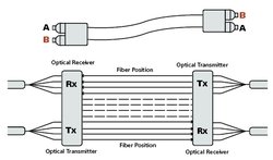
The exterior form factor of an MPO fiber connector includes a molded, rectangular plastic housing that is “keyed” on one side for mating and fiber position orientation. When this key is in the “up” position, fiber 1 is located on the left side. The MPO connector housing utilizes a push-pull latching mechanism with an audible click, which makes connection fast and reliable. The density for MPO connector applications can vary between 8, 12, 24, 32 or 48 fibers, as well as 60 and 72 fiber options for specialty high-density applications. The 12 and 24 fiber options are the most commonly used today with the 12-fiber connector (MPO-12) being the first to gain widespread acceptance in data center applications. The 24-fiber connector has proven to be a mathematically convenient solution for many 40 Gig (8 fiber) and 100 Gig (24 fiber) equipment connections, which has led to a recent increase in MPO-24 utilization. Although the connector housing size for 12 fiber and 24 fiber MPO connectors is identical, the 24-fiber option includes a second row of 12 fibers. Similarly, the 48 and 72 fiber MPO connectors include 4 and 6 rows of fibers, respectively. The 16 and 32 fiber MPO connectors contain 16 fibers in each row rather than 12. This format has been developed specifically for 400 Gig applications. MPO technology can be used for multimode as well single-mode fiber. Multimode connectors use flat ferrules while the single-mode connectors employ eight-degree angled ferrules to minimize back-reflection. Since these connectors are similar in form but incompatible with one another, color-coding is used to easily distinguish one type from the other.
Although the terms MPO and MTP are sometimes used interchangeably, MTP is the trade name for a specific multi-fiber connector produced by US Conec and stands for “Multi-fiber Termination Push On”. Among the proprietary design features inherent to MTP connectors are floating ferrules that improve alignment and performance under load conditions and elliptical guide pins for optimized alignment and durability. Mechanical upgrades within the connector housing also improve reliability. This includes a modified spring design that improves ribbon clearance and a removable housing to facilitate connector gender modification and ferrule polishing in the field, as well as improved test access. All MTP connectors are also MPO connectors, although the opposite is not true. An MTP connector is 100% inter-mateable with its generic MPO-style counterpart, but an MPO connector is not functionally equivalent to an MTP in high-performance applications, based on the tighter design tolerances and feature-set differences. The MTP connector is compliant to the same U.S. and international standards applicable to the standard MPO connector. An “Elite” version of the MTP connector is also available with reduced insertion loss compared to the standard MTP connector.
Cleaning and inspection to control MPO connector contamination are essential best practices. Each of the multiple fibers attached to an MPO connector extends a small distance from the ferrule, meaning fiber ends physically touch when the MPO connectors are mated. This makes the cleanliness of these mating surfaces crucial. The large MPO surface area and bulkhead access can provide ample opportunities for contamination to infiltrate the connector. The quantity of fiber end surfaces also increases the potential for contamination exponentially. For example, if we assume each fiber surface has a 90% chance of being contaminated, this becomes a 0.9012 or 28% chance that at least one fiber surface in an MPO-12 will be contaminated. Contamination on one fiber end can impact the others detrimentally by introducing Fresnel air gaps that propagate down the line or shift adjacent fibers out of alignment. Each fiber end-face should be inspected for the presence of dust, oil, scratches or any other contaminants. If any contamination is detected, cleaning with a purpose-built MPO cleaning tool and solution is the next logical step because the wrong cleaning tool can damage the end face. After cleaning, an additional re-inspection for verification purposes should be performed prior to installation. This cleaning-inspection cycle should be repeated until no contamination is detected. Get more fiber inspection best practices.
The term polarity in optical networks is used to describe the correct matching of fibers between the transmitting and receiving ends of the optical link. MPO connectors can complicate polarity issues due to the increased density of fibers within each connector. Unlike an SC or LC fiber connection, a simple VFL check cannot fully verify polarity or continuity. Because fiber positions are fixed within each connector, the fibers cannot simply be moved if a polarity issue is detected. Adding additional complexity, MPO connectors have adopted three different polarity methods. Type A: Known as the straight-through method. Using this polarity convention, the first connector in the “key up” position will route to the second connector in the “key down” position. In this orientation, the fiber in position 1 of the first connector will route to fiber position 1 in the adjacent connector, along with fibers 2, 3, 4, etc.

Type B: This is sometimes referred to as the inverted or “flipped” method. In this configuration, both connectors are in the “key up position”, but the numbering of corresponding fibers will be reversed. For example, using MPO-12 connectors, fiber 1 from the first connector will be connected to fiber position 12 in the second connector, and fiber 2 will be connected to fiber position 11, etc. This convention is commonly used in 40/100G architecture.

Type C: This is also called the twisted pair or “pairwise flip” method. Since each grouping of 2 fibers is flip-flopped, fiber 1 will connect to the fiber 2 location of the adjacent connector while fiber 2 will be routed to the fiber 1 location. The same switching applies to each discrete pair of fibers. This configuration is often found in 1/10G architecture.

An ideal fiber optic connection will perfectly align the fibers so that no optical energy is lost. Unfortunately, the manufacturing tolerances inherent to both the connectors and the fibers themselves make this perfect alignment condition virtually impossible.

Simplex fiber connections capture two mating cylindrical fiber ends within a cylindrical ceramic split-sleeve, making alignment of the mating fibers quite straight-forward. MPO connectors present the combined challenges of simultaneous multi-fiber alignment and adapter open channels that separate one connector from the other. The multiple fiber positions contribute to tolerance stack-up because the distance and spacing between each fiber creates opportunities for lateral offset and other potential misalignment conditions. To achieve optimal alignment, MPO fiber connectors utilize two stainless steel alignment pins on one connector and two holes in the same relative position on the mating part. These are also referred to as “male” and “female” configurations, although the nomenclature of “pins” and “no pins” is commonly used. Some manufacturers do provide connector options with removable/replaceable pins, although most connectors in either state cannot be changed in the field, meaning two connectors of the same type cannot be mated to one other. MPO test equipment that can accept either pinned or unpinned connectors can simplify alignment/configuration issues encountered in MPO testing. During reference verification testing, pinned jumpers can be used to complete the circuit between two unpinned cable connector terminations.
Although fiber misalignment can significantly impact insertion loss associated with the MPO connector interface, other factors including fiber geometry mismatches and the Fresnel reflection induced by air gaps or contamination can also contribute to the overall MPO connector loss. Since many of the contributing factors to optical loss are related to mechanical limitations or connector tolerances, high-performance connectors may be considered when loss budgets are low and density is high. Test equipment designed with an option to perform optical loss testing on MPO-terminated cables is highly recommended because this reduces the complexity involved in testing MPOs with a single channel OLTS.

Our Advantages

Pre-connectorized assemblies

Pre-connectorized MPO/MTP assemblies for reduced installation time with plug & play functionality.

Optimized air circulation

Ribbon cable MPO/MTP Patch cords, FanOuts and Harness‘ with a reduced cable diameter consuming less space in cable ducts, conduits and path ways for optimized air circulation in raised-floors.

Fast Installation

Easy moves, adds and changes due to scalability and modularity of the product design for reduced down-times and faster installation.

Polarity A

In order to offer users the migration path from 10 Gbit/s to 40 Gbit/s the Telegärtner MPO/MTP product family refers to polarity A.

High Performance and Quality

Factory-assembled with measurement report for high, enduring reliability and performance.