


Common MPO Architectures of 1G/10G/25G/40G/100G
The versatility of MPO technology makes it a very scalable design solution that can be used in a variety of different architectures. With our understanding of backbone, links and channels in the background, we can consider several possible MPO architectures.
This section highlights seven of the most common scenarios. Though the wide variety of configurations may seem intimidating at first, they represent three basic types of networks. In each scenario, a backbone trunk with MPO connectors is used. As the bandwidth demands increase, so does the amount of MPO connectivity. For continuity purposes, these scenarios all show a connection between servers and switches, however, please keep in mind that MPO can also be used for connectivity between different types of equipment (such as switch-to-switch).
1G/10G MM Channels and 1/10/100G SM Channels
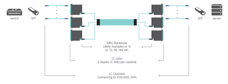
Scenario 1: LC-LC Links (LC-LC Channels)
In the figure below, notice the MPO backbone connected through to cassettes, and the cassettes break down into individual LC links and LC channels when equipment cords are added. When the requirement is to run up to 25G multimode and up to 200G singlemode, using an MPO backbone is much more efficient than running numerous individual LC duplex pairs. In this example the designer chose to run a 72 fiber trunk, and break it into 36 duplex LC links using cassettes. In this scenario, you don’t need to test the backbone fiber, but you will test the link at the front of the LC cassettes.
Scenario 2: LC-MPO Links (LC-LC Channels)
Note that the architecture example below is nearly the same as the first example. The difference is that the link on the server side (as shown in the diagram) remains as MPO connectivity and then breaks out to LC after the link with an MPO-LC breakout cable. This is a good design choice when equipment rack-space is at a premium. In this sort of design scenario, also consider the tradeoff of flexibility. At the server end, there is opportunity for more density, and a cleaner solution. However, on the LC cassette side (the left side of the diagram), there’s still a fiber density challenge. In this scenario, one end of your link test will be LC while the other end will be MPO.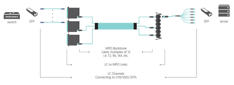
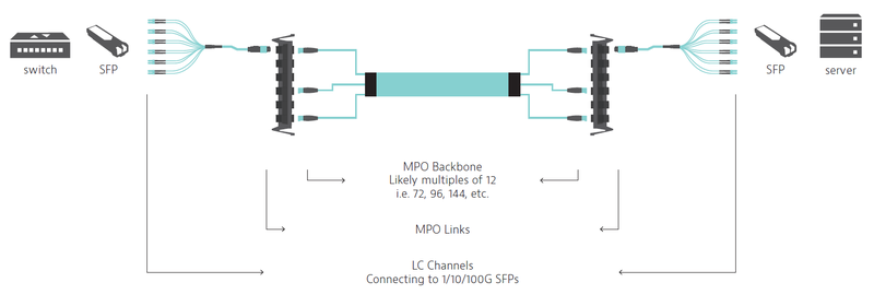
Scenario 3: MPO-MPO Links (LC-LC Channels)
In the figure below, notice that the LC channels are the same as the other configurations. But rather than feeding your equipment with LC connectivity, there is MPO connectivity on both ends of the link. This provides for much more density at the patch panel on each end of the channel. The fiber management is neat and clean at the racks. However, as stated above, this may hinder flexibility. If there is a need to make changes at the switch end, an entire fan-out cable may need to be replaced. In this scenario, both ends of your link test will be MPO.
40/100Gbps to 10/25/Gbps
As mentioned in the Lanes and Speeds section, most of the 40/100Gbps architectures only need four lanes (or eight total fibers) of an MPO connector. While the backbone is similar to some 1/10G applications, changes start occurring with the channels as the equipment on the servers and switches begin using QSFP transceivers in places.
Scenario 1: MPO-MPO Links (MPO-LC channels)
In the figure below, notice that the backbone remains MPO-MPO (like scenario 3). The change here occurs in the channels. The switch (on the left side) now has dedicated QSFP transceivers that an MPO equipment cord can be plugged into. The servers (on the right side) use breakout cables that break the MPO connection out into 4 duplex LC pairs (8 fibers). In this scenario, both ends of your link test will be MPO.
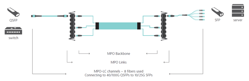
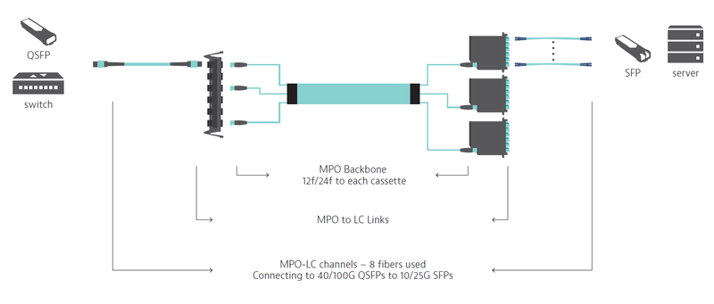
Scenario 2: MPO-LC Links (MPO-LC channels)
In this scenario, note the QSFP at the switch end (on the left side of the diagram). From the backbone the fiber connects into a cassette and breaks down into individual LC connections at the server (as shown on the right side of the diagram). Imagine standing in front of a rack full of four servers. One server on the top, two in the middle, and one on the bottom. In order to achieve 10 or 25G connectivity, place the LC cassette at the top of the rack, run a duplex LC pair down to the bottom server, a duplex LC pair to the third position server, a duplex LC pair down to the second position server, and a duplex LC pair down to the top server. This design is typically used when equipment rack-space is at a premium. In this scenario, one end of your link test will be MPO while the other end will be LC.
40/100G SR4 (MM) and 100G PSM4 (SM)
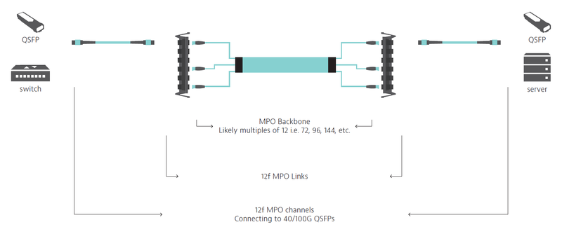
Scenario 1: MPO-MPO Links (MPO-MPO channels)
If you are looking to build out a simpler 40 or 100G solution using short-reach four lane technology (SR4), you can replace both ends of the channel with MPO to MPO connectivity. The active equipment uses a Quad Small Form-factor Pluggable transceiver (QSFP) to achieve end to end 40/100G. In this scenario, both ends of your link test will be MPO and you will test only 8 fibers rather than 12.
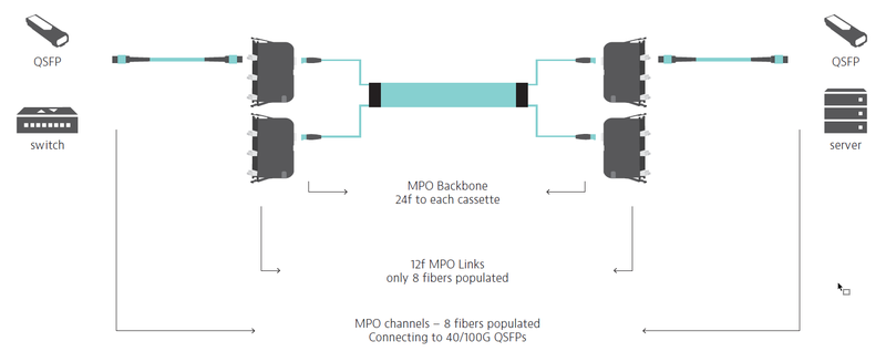
Scenario 2: MPO-MPO Links (MPO-MPO channels)
This scenario provides a true high-density 40/100G solution using a combination of different MPO connections. The backbone cable will deliver a series of 24 fiber MPO connectors that each plug into a cassette. Each cassette will break down into three separate, eight fiber connectivity to the QSFP. From a layout perspective this example is no different than scenario example 3, but there are considerations from a testing perspective. In this scenario, both ends of your link test will be MPO and you will test only 8 fibers rather than 12.